Problem z kimenatyką

Dyskusje dotyczące działania obsługi programu LinuxCNC
Awatar użytkownika

Autor tematu
k-m-r1
ELITA FORUM (min. 1000)
Posty w temacie: 6
Posty: 1418
Rejestracja: 23 cze 2008, 10:38
Lokalizacja: OOL lub DW
Kontakt:

Problem z kimenatyką

#1

Post napisał: k-m-r1 » 01 maja 2015, 16:35

Mam pewien problem gdyż mam robot scara którym chce sterować prze linuxa tylko nie potrafię znaleźć plików kinematyki gdyż opisy są do EMC a teraz jest linuxcnc i nie widzę tych plików na dysku.

Szukałem katalogów, szukałem lików...

Kod: Zaznacz cały

kinematics$ ls
blend.fig     genhexkins.h  pumakins.c    tc.c          trivkins.c
cubic.c       genserkins.c  pumakins.h    tc.h
cubic.h       genserkins.h  rotatekins.c  tp.c
gantrykins.c  kinematics.h  scarakins.c   tp.h
genhexkins.c  maxkins.c     Submakefile   tripodkins.c
i porostu nie ma lub ja czegoś nie wiem.
Z opisu do EMC wynika że scarakins.c zawiera dane członów robota i ja muszę zmienić długość ramion na 280.


MACH3 cncTworzenie Makr do palników magazynków THC OHC inneEKRANY dla firm producentów maszyn Budowa sprzedaż wypalarki plazma gaz obrotnice Elektrodrążarki Frezarki Tokarki Giętarki3D inne wg zlecenia 888 703 196 Tomek Komor [email protected]


micges
Specjalista poziom 1 (min. 100)
Posty w temacie: 3
Posty: 291
Rejestracja: 08 sty 2010, 02:04
Lokalizacja: Toruń

#2

Post napisał: micges » 01 maja 2015, 20:06

W pliku hal zmieniasz

Kod: Zaznacz cały

loadrt trivkins
na

Kod: Zaznacz cały

loadrt scarakins
w następnej linii

Kod: Zaznacz cały

setp scarakins.D1 280
- ustawia długość pierwszego ramienia na 280, w kolejnej linii analogicznie D2 i tak dalej aż do D6

Awatar użytkownika

Autor tematu
k-m-r1
ELITA FORUM (min. 1000)
Posty w temacie: 6
Posty: 1418
Rejestracja: 23 cze 2008, 10:38
Lokalizacja: OOL lub DW
Kontakt:

#3

Post napisał: k-m-r1 » 01 maja 2015, 20:28

A gdzie jest plik którego szukam?
MACH3 cncTworzenie Makr do palników magazynków THC OHC inneEKRANY dla firm producentów maszyn Budowa sprzedaż wypalarki plazma gaz obrotnice Elektrodrążarki Frezarki Tokarki Giętarki3D inne wg zlecenia 888 703 196 Tomek Komor [email protected]


micges
Specjalista poziom 1 (min. 100)
Posty w temacie: 3
Posty: 291
Rejestracja: 08 sty 2010, 02:04
Lokalizacja: Toruń

#4

Post napisał: micges » 01 maja 2015, 21:06

Może od początku: jak sterowany jest robot? masz sprzęt do sterowania nim czy chcesz pierw się pouczyć?

Awatar użytkownika

Autor tematu
k-m-r1
ELITA FORUM (min. 1000)
Posty w temacie: 6
Posty: 1418
Rejestracja: 23 cze 2008, 10:38
Lokalizacja: OOL lub DW
Kontakt:

#5

Post napisał: k-m-r1 » 01 maja 2015, 21:16

robot sterowany jest z windows + klon arduino, prosty program gdzie podajesz punkty i jedzie z punktu do punktu nic więcej
taka pokazowa maszynka

Robot to 2 silniki krokowe + sterowniki

Chce osiągnąć sterowanie i wykonywanie prostego g-kodu g0 g1 g2 g3... w płaszczyźnie x-y +marker znaczący ścieżkę poruszania ramienia po kartce.

Tyle na początek to takie minimum.

[ Dodano: 2015-05-01, 21:18 ]
Może to dziwne ale jestem ciekaw i odpowiedź wpisz tak i siak jest OK jednak ciekawość mnie zjada i draże temat dlatego szukam pliku kinematyki bo może sam będę chciał coś zmienić dopisać, wykombinować za jakiś czas :)
MACH3 cncTworzenie Makr do palników magazynków THC OHC inneEKRANY dla firm producentów maszyn Budowa sprzedaż wypalarki plazma gaz obrotnice Elektrodrążarki Frezarki Tokarki Giętarki3D inne wg zlecenia 888 703 196 Tomek Komor [email protected]


micges
Specjalista poziom 1 (min. 100)
Posty w temacie: 3
Posty: 291
Rejestracja: 08 sty 2010, 02:04
Lokalizacja: Toruń

#6

Post napisał: micges » 01 maja 2015, 21:36

Jeżeli chesz tym sterować to odłącz arduino, podłącz step/dir krokówek pod LPT, postaw/uruchom hybrid iso na jakiejs plycie głównej z portem LPT lub użyj karty LPT na PCI. Po zainstalowaniu systemu uruchom program stepconf który od A do Z skonfiguruje Ci maszynę XYZ sterowaną z portu LPT. Potrzebny tam będzie adres bazowy LPT, jeśli jest na płycie głównej to nie ma problemu. Jeśli użyjesz portu LPT na PCI, otwórz terminal, wykonaj polecenie

Kod: Zaznacz cały

lspci -vv
na liście urządzeń znajdź swoją kartę LPT, pod nią będą wyświetlone wszystkie adresy bazowe, zapisz je gdzieś.
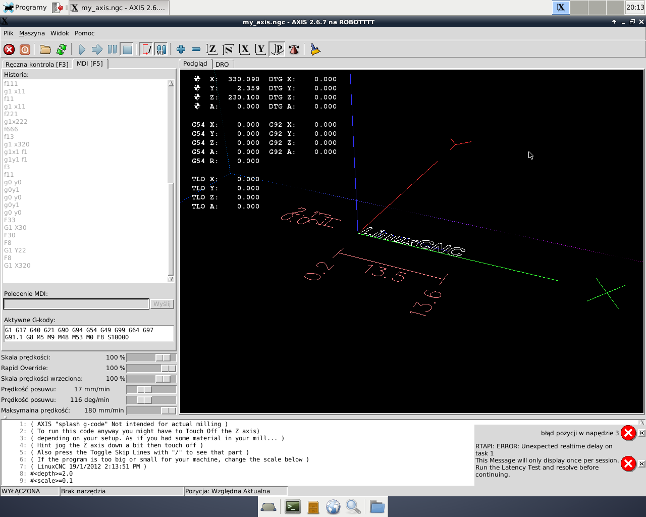
Po zapisaniu uruchom Twoją konfigurację ze skrótu na pulpicie który się pojawi. Przetestuj czy silniki się kręcą. Jeśli się nie kręcą, uruchom stepconf, wczytaj Twoją konfigurację, zmień adres bazowy na kolejny z listy, zapisz i ponownie przetestuj.
Jak wszystko będzie w porządku otwórz w edytorze plik *.hal z katalogu gdzie wygenerowałeś konfigurację ze stepconf i wprowadź zmiany które napisałem wcześniej. Do tego co chcesz robić nie potrzeba plików źródłowych.

Awatar użytkownika

Autor tematu
k-m-r1
ELITA FORUM (min. 1000)
Posty w temacie: 6
Posty: 1418
Rejestracja: 23 cze 2008, 10:38
Lokalizacja: OOL lub DW
Kontakt:

#7

Post napisał: k-m-r1 » 01 maja 2015, 22:08

Komp to stacjonarka stary ibm z Pentium4 LPT jest na płycie.

Ostatnio sporo czytałem o linuxicnc i na dziś mi styknie bo literki uciekają.

Teraz już mam jasną sytuacja. Będę jeszcze dopytywało kompilacje gdy odpale robota.
MACH3 cncTworzenie Makr do palników magazynków THC OHC inneEKRANY dla firm producentów maszyn Budowa sprzedaż wypalarki plazma gaz obrotnice Elektrodrążarki Frezarki Tokarki Giętarki3D inne wg zlecenia 888 703 196 Tomek Komor [email protected]

Awatar użytkownika

Autor tematu
k-m-r1
ELITA FORUM (min. 1000)
Posty w temacie: 6
Posty: 1418
Rejestracja: 23 cze 2008, 10:38
Lokalizacja: OOL lub DW
Kontakt:

#8

Post napisał: k-m-r1 » 14 maja 2015, 17:19

Obecnie robot działa czyli ramiona poruszają się podczas sterowania ręcznego w lewo i prawo

Po wykonaniu bazowania i G1 X12 F12 pojawia sie komunikat

Błąd w napędzie 1
Podobnie dzieje sie z innymi osiami i podobne komunikaty są.


Silnik szarpnie i na ekranie wyłączone zostaje" napięcie" ikonka ON

Gdzie jest problem?

[ Dodano: 2015-05-14, 18:15 ]
Obrazek
MACH3 cncTworzenie Makr do palników magazynków THC OHC inneEKRANY dla firm producentów maszyn Budowa sprzedaż wypalarki plazma gaz obrotnice Elektrodrążarki Frezarki Tokarki Giętarki3D inne wg zlecenia 888 703 196 Tomek Komor [email protected]


tomcat65
ELITA FORUM (min. 1000)
Posty w temacie: 1
Posty: 1236
Rejestracja: 15 lis 2009, 02:46
Lokalizacja: Olsztyn
Kontakt:

#9

Post napisał: tomcat65 » 15 maja 2015, 10:30

U mnie taki błąd wyskakuje, jak przegnę z szybkością posuwu osi.

Awatar użytkownika

Autor tematu
k-m-r1
ELITA FORUM (min. 1000)
Posty w temacie: 6
Posty: 1418
Rejestracja: 23 cze 2008, 10:38
Lokalizacja: OOL lub DW
Kontakt:

#10

Post napisał: k-m-r1 » 15 maja 2015, 22:18

micges, pomógł w ustawieniach.

Swoją drogą zaufałem Stepconfig i wyprowadził mnie w ...

tomcat65,

Na podobną informacje trafiłem drążąc temat.

Informacje pomocne będą potomnym
http://wiki.linuxcnc.org/cgi-bin/wiki.p ... wing_Error

Kod: Zaznacz cały

Following Error Definition

While an axis is in motion, the EMC sends commands for current position. We call this commanded position. It is where the axis is supposed to be. Whenever a drive receives a velocity command it takes a bit for it to get up to that velocity and move to the commanded position. The difference between commanded and actual is following error. Commanded and actual position ought to be the same for an ideal machine. Inertia and such get in the way and add to following error.

EMC checks to see whether the commanded position is within range of the actual position. If this error is out of range, you get an error message something like:

Joint 0 following error.

When this error pops up you can be pretty certain that there are problems with the way you ini file is set.

Following Error Trip Ramp

The EMC ini file uses two variables, FERROR and MIN_FERROR to define acceptable following error for each axis. Think of MIN_FERROR as the following error allowed at very low velocity and FERROR as the distance allowed during rapid moves.

The graph shown below approximates what the following error trip line looks like when FERROR is set to 1 and MIN_FERROR is set to 0.01. MAX_Velocity for this graph has been set to 500. I did not set any units here and that is deliberate. My first reason is that the meaning of trip line will follow the units used for velocity, which follows the units that are defined for the axis in the ini. If that unit is inches, then the velocity is in inches per second and the trip line is related to that unit. The second reason I didn't assign units to the graph is that I am not completely certain what the units of Ferror and Min_Ferror.

You should think of any following error to the left of the diagonal line as acceptable for that velocity . If you look at 250 units velocity (the green lines) any following error less than half way between FERROR and MIN_FERROR is acceptable and will not trip out axis motion. If you increase the velocity to 400 and draw a similar pair of lines there, it will include all acceptable following errors at that velocity.

In my thinking, I simply assume that the ferror numbers are a percent of the unit value defined in the ini file. In the case of this graph and the numbers I assigned to generate it, I'd assume one percent of 500 for the permitted following error during a rapid move. If the unit defined for this axis is mm, then following error at rapid could be as much as 5 mm. If inches, then these would permit as much as five inches. (We should get one of the code gurus to give us an interpretation of the actual computation done for this)

Correction: The units of Ferror and Min_Ferror are the same as the units of length used for that axis. So if your axis is in inches, and your Ferror is 1, that means an error of 1 inch will cause it to trip. Likewise, if Min_Ferror is 0.01, then an error of 0.01 inches will trip it at low speed.

I hear someone asking, "Do you consider 5 inches off from commanded to be acceptable. Hey even the enhanced GPS that's being used to guide field tractors is more accurate than that." The whole point of the following error trip as set up in the EMC is to constrain following error and cause the machine to fail if it's error is greater than some known value. By using both FERROR and MIN_FERROR the integrator is able to define values that are acceptable for their machine. I know that I'd want my own machines to be closer than 5 inches at most any speed.

Following Error and Stepper Driven Machines

The concept of a following error is funny when talking about stepper motors. Since they are an open loop system, there is no position feedback to let you know if you actually are out of range.

following errors usually have 2 causes on steppers

1. too little ferror or min_ferror

2. the RT pulsing can't keep up with the speed needed

2.a. BASE_PERIOD set incorrectly or (requested step rate is not possible at this BASE_PERIOD)

2.b. max velocity too high

2.c. max acceleration too high 
MACH3 cncTworzenie Makr do palników magazynków THC OHC inneEKRANY dla firm producentów maszyn Budowa sprzedaż wypalarki plazma gaz obrotnice Elektrodrążarki Frezarki Tokarki Giętarki3D inne wg zlecenia 888 703 196 Tomek Komor [email protected]

ODPOWIEDZ Poprzedni tematNastępny temat

Wróć do „LinuxCNC (dawniej EMC2)”