Strona 1 z 1

Ploter tnąco-bigujący modernizacja

: 05 sty 2017, 12:37
autor: tytustytus
Witam wszystkich,
Zwracam się w użytkowników z pytaniem dotyczącym modernizacji plotera tnąco-bigującego. Otóż mam taki ploter z uszkodzonym systemem sterowania opartym na kartach. Chciałbym wymienić sterowanie na nowe sterowniki do silników lub serwa. Chciałbym żeby wszystkim sterował LinuxCNC.

I tutaj pojawia się pytanie, w jaki sposób sterować takim ploterem na którego głowicy umieszczone są dwa narzędzia?
Zakładam że generuje plik dxf-a, generuje g-code i teraz chciałbym żeby najpierw zrobił mi bigowanie a później cięcie tylko jak ustawiać takie parametry w Linuxie? czy do tego typu prac jest jakiś offset którym mogę to ustawić?

Będę wdzięczny za pomoc

: 05 sty 2017, 15:52
autor: adam Fx
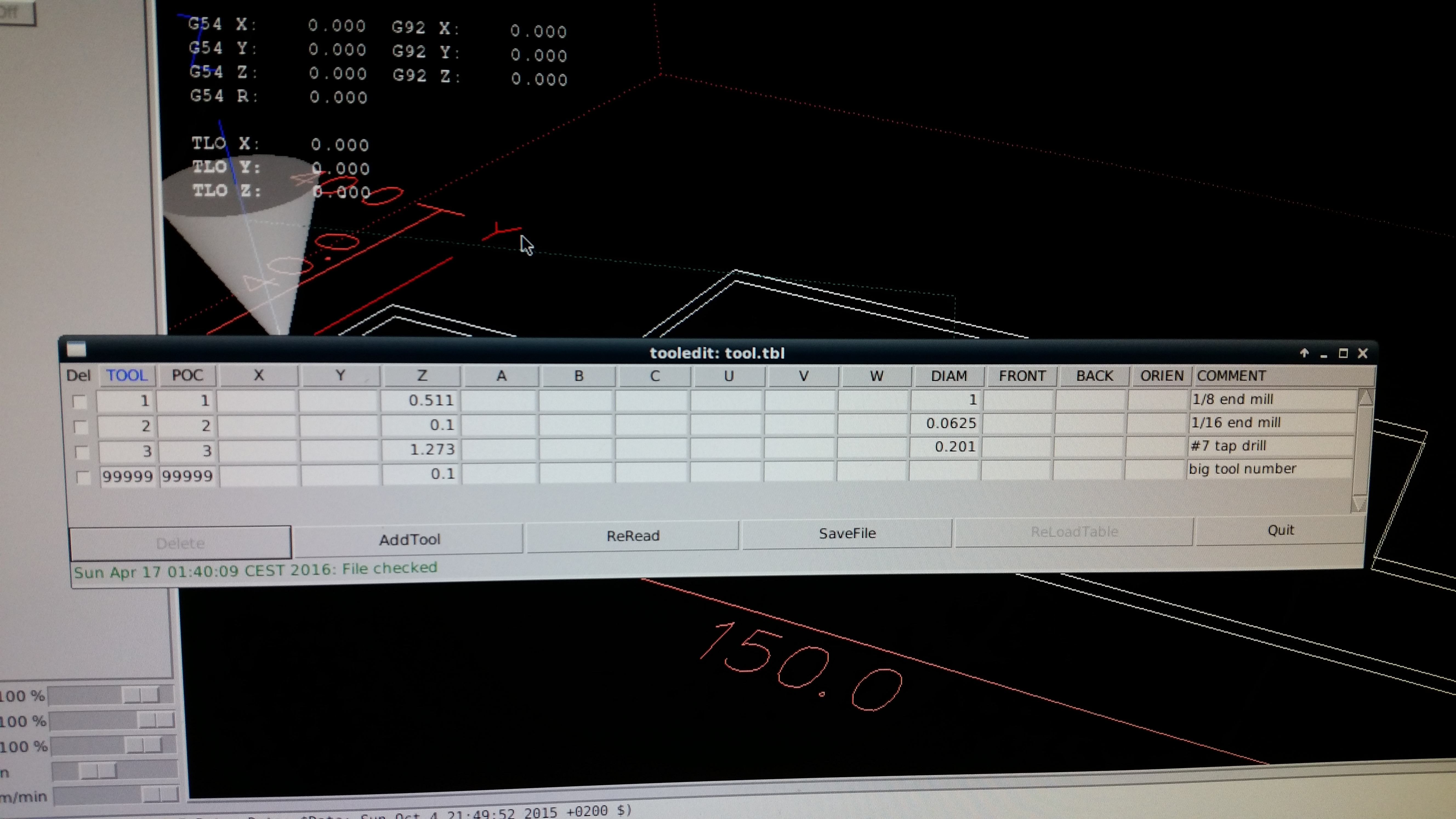
tu zwyczajnie rozwiązałem to przez zmianę narzędzia - w tablicy narzędzi można podać różnicę w każdej osi względem narzędzia zerowego więc najpierw idzie sobie T1 z XY 0 a potem wywołuje T2 i na ten moment mam już poprzesuwane współrzędne pod głowicę gwintującą.

: 06 sty 2017, 11:18
autor: tytustytus
Dziękuje za podpowiedź, rzeczywiście proste i skuteczne, mam tutaj jednak pytanie co do przygotowywania programu dla takiej tablicy narzędzi.
czy przy każdej zmianie narzędzia w programie konieczne jest zerowanie?
Czy mogę sobie po prostu w cambam-ie przygotować program że te elementy robię tym narzędziem al inne innym i ta zmiana nastąpi bezproblemowo?

: 06 sty 2017, 16:30
autor: adam Fx
Zerować nie musisz- podasz w tablicy tylko jaka jest różnica w odległościach XYZ między narz. nr1 i LinuxCNC sam sobie przeliczy.
NP.
Najazd narz. 1 na punkt X0 Y0
Zmiana na narz.2
i gdy znowu podasz G0 X0 Y0 to teraz narzędzi nr.2 przejedzie w to miejsce gdzie przed chwilą stało narzędzie nr1

: 08 sty 2017, 10:04
autor: tytustytus
Co do tablicy narzędzi już wiem jak to zrobić, mam natomiast jeszcze jeden problem, mianowicie wraz ze zmianą narzędzia na linuxie konieczne będzie wysterowanie siłowników pneumatycznych opuszczających dane narzędzie. Czy jest możliwość sterowania z poziomu g-kodu wyjściami portu LPT tak żebym mógł zmieniając dane narzędzie wysterować odpowiadający mu elektrozawór?

: 08 sty 2017, 21:56
autor: adam Fx
Tak- dodając dodatkowe komendy M - tak steruje tum uchwytem

http://wiki.linuxcnc.org/cgi-bin/wiki.pl?M100-199

: 14 sty 2017, 08:56
autor: tytustytus
Witam,
zgłębiłem trochę temat i przyznam że dość poważnie myślę o sterowniku CSMIO, po kontakcie z firmą oraz po przeczytaniu specyfikacji wiele wskazuje że ten sterownik jest naprawdę dobrym pomysłem.

Czy miał ktoś może jakieś doświadczenie związane z tym sterownikiem?

: 14 sty 2017, 14:10
autor: k-m-r1
CSmio i Linux tosz to sie nie da

: 17 sty 2017, 06:28
autor: tytustytus
W tym przypadku jestem skłonny zrezygnować z Linuxa na rzecz Macha jeśli mi to pomoże w lepszej obsłudze noża wraz z rolką bigującą.

Przy okazji mam jeszcze jedno pytanie, czy może mi ktoś podpowiedzieć gdzie szukać opisów tego typu kodu wygenerowanego na maszynę do obróbki tektury:

Kod: Zaznacz cały

.(
PU;
SP3;
VS40
PU;PA57200,112704
PD;VS30
PA57200,117555
VS31
PU;PA66040,117555
PD;VS30
PA66040,112704
VS20
PU;PA71200,112704
PD;VS30
PA71200,117555
VS31
PU;PA80040,117555
PD;VS30
PA80040,112704
VS35
PU;PA90200,112704
PD;VS30
PA90200,117555
VS31
PU;PA99040,117555
PD;VS30
PA99040,112704
VS20
PU;PA104200,112704
PD;VS30
PA104200,117555
VS31
PU;PA113040,117555
PD;VS30
PA113040,112704
VS40
PU;PA113040,126732
PD;VS30
PA113040,131583
VS31
PU;PA104200,131583
PD;VS30
PA104200,126732
VS20
PU;PA99040,126732
PD;VS30
PA99040,131583
VS31
PU;PA90200,131583
PD;VS30
PA90200,126732
VS35
PU;PA80040,126732
PD;VS30
PA80040,131583
VS31
PU;PA71200,131583
PD;VS30
PA71200,126732
VS20
PU;PA66040,126732
PD;VS30
PA66040,131583
VS31
PU;PA57200,131583
PD;VS30
PA57200,126732
VS40
PU;PA57200,140760
PD;VS30
PA57200,145611
VS31
PU;PA66040,145611
PD;VS30
PA66040,140760
VS20
PU;PA71200,140760
PD;VS30
PA71200,145611
VS31
PU;PA80040,145611
PD;VS30
PA80040,140760
VS35
PU;PA90200,140760
PD;VS30
PA90200,145611
VS31
PU;PA99040,145611
PD;VS30
PA99040,140760
VS20
PU;PA104200,140760
PD;VS30
PA104200,145611
VS31
PU;PA113040,145611
PD;VS30
PA113040,140760
VS40
PU;PA220520,146897
PD;VS30
PA232820,146897
VS9
PU;PA233220,145695
PD;VS30
PA220520,145695
VS8
PU;PA219720,145294
PD;VS30
PA208720,145294
VS40

: 18 sty 2017, 20:39
autor: k-m-r1

Kod: Zaznacz cały

HPGL (czasami pisany również jako HP-GL, ang. Hewlett-Packard graphics language) – język stworzony do sterowania drukarką. Pierwotnie język obsługi drukarki stosowany w ploterach firmy Hewlett-Packard. Obecnie jest standardem dla prawie wszystkich ploterów. W pewnym zakresie został wbudowany do PCL dla drukarek laserowych.

Język ten składa się z serii dwuliterowych kodów oraz następujących po nich opcjonalnych parametrów.

Kod: Zaznacz cały

HPGL
From Wikipedia, the free encyclopedia
	This article needs additional citations for verification. Please help improve this article by adding citations to reliable sources. Unsourced material may be challenged and removed. (September 2016) (Learn how and when to remove this template message)

HP-GL (Hewlett-Packard Graphics Language; often written as HPGL) is a printer control language created by Hewlett-Packard (HP). HP-GL was the primary printer control language used by HP plotters.[1] It later became a standard for almost all plotters. Hewlett-Packard's printers also usually support HPGL in addition to PCL.

Contents

    1 Design
    2 Examples
    3 HP-GL/2
    4 AGL
    5 See also
    6 References
    7 External links

Design

The language is formed from a series of two letter codes, followed by optional parameters. For instance an arc can be drawn on a page by sending the string:

AA100,100,50;

This means Arc Absolute, and the parameters place the center of the arc at absolute coordinates 100,100 on the page, with a starting angle of 50 degrees measured counter-clockwise. A fourth optional parameter (not used here) specifies how far the arc continues, and defaults to 5 degrees.

When first introduced, HPGL contained the following commands:
Command 	Meaning
Vector Group
PA x,y{,x,y{...}} 	Plot absolute [i]
PR x,y{,x,y{....}} 	Plot relative [i]
PD 	Pen down
PU 	Pen up
Character Group
CA n 	Designate alternate character set n [i]
CP spaces, lines 	Character plot [d]
CS m 	Designate standard set m [i]
DI run, rise 	Absolute direction [d]
DR run, rise 	Relative direction [d]
LB c, ..., c 	Label ASCII string [c]
SA 	Select alternate character set
SI wide, high 	Absolute character size [d]
SL tan θ 	Absolute character slant (from vertical) [d]
SR wide, high 	Relative character size [d]
SS 	Select standard character set
UC x, y, pen{, ...} 	User defined character [i]
Line Type Group
LT t{,l} 	Designate line type t and length l [d]
SM c 	Symbol mode [c]
SP n 	Select pen [i]
VA 	Adaptive velocity
VN 	Normal velocity
VS v{,n} 	Select velocity v for pen n [i]
Digitize Group
DC 	Digitize clear
DP 	Digitize point
OC 	Output current position and pen status
OD 	Output digitized point and pen status
Axes
TL tp{,tn} 	Tick length [d]
XT 	X axis tick
YT 	Y axis tick
Set-Up Group
IP p1x,p1y,p2x,p2y 	Input p1 and p2 [i]
IW xlo,ylo,xhi,yhi 	Input window [i]
OP 	Output p1 and p2 [i]
Configuration Status
AP 	Automatic pen pickup [i]
DF 	Set default values
IM e{,s{,p}} 	Input e, s and p masks [i]
IN 	Initialize
OE 	Output error [i]
OS 	Output status [i]

Formats:

    [i]: integer formats between -32767 and 32768. No decimal point.
    [d]: decimal format between +/- 127.9999. Optional decimal point.
    [c]: ASCII character

Examples

Typical HP-GL files start with a few setup commands, followed by a long string of graphics commands. The file was in ASCII (text file) format, for instance:
An example HP-GL file Command 	Meaning
IN; 	initialize, start a plotting job
IP; 	set the scaling points (P1 and P2) to their default positions
SP1; 	select pen 1
PU0,0; 	lift Pen Up and move to starting point for next action
PD100,0,100,100,0,100,0,0; 	put Pen Down and move to the following locations (draw a box around the page)
PU50,50; 	Pen Up and move to X,Y coordinates 50,50
CI25; 	draw a circle with radius 25
SS; 	select the standard character set
DT*,1; 	set the text delimiter to the asterisk, and do not print them (the 1, meaning "true")
PU20,80; 	lift the pen and move to 20,80
LBHello World*; 	draw a label
LTlinetype,length 	set line type and its repetition length
CSxx 	set character set (e.g. 33 is German)
DIx,y 	set direction of text given as the catheti
SIww,hh 	set character width and height

The coordinate system was based on the smallest units one of the HP plotters could support, and was set to 25 µm (i.e. 40 units per millimeter, 1016 per inch). The coordinate space was positive or negative floating point numbers, specifically ±230.
HP-GL/2
The original HP-GL language did not support definition of line width, as this parameter was determined by the pens loaded into the plotter. With the advent of the first inkjet plotters, line width for the "pens" specified within the HP-GL files had to be set at the printer so it would know what line width to print for each pen, a cumbersome and error-prone process. With HP-GL/2, definition of line width was introduced into the language and allowed for elimination of this step. Also, among other improvements a binary file format was defined that allowed for smaller files and shorter file transfer times, and the minimal resolution was reduced.
https://es.wikipedia.org/wiki/HPGL

https://en.wikipedia.org/wiki/HPGL

http://cstep.luberth.com/HPGL.pdf

http://h20566.www2.hp.com/hpsc/doc/publ ... a-bpl13211

http://www.sxlist.com/techref/language/ ... mmands.htm

http://cstep.luberth.com/hpgl.htm