pascalPL pisze:Hmm.. a w EMC2 jako port lpt konfiguruje niby /dev/ttyUSB0 ? Nie czaje troszkę tego "translatora" lpt->usb .
...tutaj pomyśle z arduino jest nieco inaczej
komunikacja z HALem jest przez aplikację user-space w pytonie
arduino.py
Kod: Zaznacz cały
#!/usr/bin/python
#    HAL userspace component to interface with Arduino board
#    Copyright (C) 2007 Jeff Epler <[email protected]>
#
#    This program is free software; you can redistribute it and/or modify
#    it under the terms of the GNU General Public License as published by
#    the Free Software Foundation; either version 2 of the License, or
#    (at your option) any later version.
#
#    This program is distributed in the hope that it will be useful,
#    but WITHOUT ANY WARRANTY; without even the implied warranty of
#    MERCHANTABILITY or FITNESS FOR A PARTICULAR PURPOSE.  See the
#    GNU General Public License for more details.
#
#    You should have received a copy of the GNU General Public License
#    along with this program; if not, write to the Free Software
#    Foundation, Inc., 59 Temple Place, Suite 330, Boston, MA  02111-1307  USA
import serial
import hal
import sys
import time

def encode(addr, data):
    if data < 0 or data > 2048: raise ValueError, "data %02d out of range" % data
    if addr < 0 or addr > 8: raise ValueError, "address %02d out of range" % addr
    b1 = 0x80 | (addr << 4) | (data >> 7)
    b2 = data & 0x7f
    return chr(b1) + chr(b2)

PORT = "/dev/ttyUSB0"

if len(sys.argv) > 1:
    PORT = sys.argv[1]

if len(sys.argv) > 2:
    nout = int(sys.argv[2])
else:
    nout = 6

if nout > 6 or nout < 0:
    raise SystemExit, "Number of digital outputs must be from 0 to 6"

pinmap = [2,4,7,8,12,13]
dacpinmap = [3,5,6,9,10,11]

ser = serial.Serial(PORT, 9600, timeout=2)

c = hal.component("arduino")
for port in range(6):
    c.newpin("analog-in-%02d" % port, hal.HAL_FLOAT, hal.HAL_OUT)
    c.newparam("analog-in-%02d-offset" % port, hal.HAL_FLOAT, hal.HAL_RW)
    c.newparam("analog-in-%02d-gain" % port, hal.HAL_FLOAT, hal.HAL_RW)
    c.newpin("analog-out-%02d" % dacpinmap[port], hal.HAL_FLOAT, hal.HAL_IN)
    c.newparam("analog-out-%02d-offset" % dacpinmap[port], hal.HAL_FLOAT, hal.HAL_RW)
    c.newparam("analog-out-%02d-scale" % dacpinmap[port], hal.HAL_FLOAT, hal.HAL_RW)
    c['analog-in-%02d-gain' % port] = 1.0
    c['analog-out-%02d-scale' % dacpinmap[port]] = 1.0
for port in range(nout):
    c.newpin("digital-out-%02d" % pinmap[port], hal.HAL_BIT, hal.HAL_IN)
    c.newparam("digital-out-%02d-invert" % pinmap[port], hal.HAL_BIT, hal.HAL_RW)
for port in range(nout, 6):
    c.newpin("digital-in-%02d" % pinmap[port], hal.HAL_BIT, hal.HAL_OUT)
    c.newpin("digital-in-%02d-not" % pinmap[port], hal.HAL_BIT, hal.HAL_OUT)
    c.newparam("digital-in-%02d-pullup" % pinmap[port], hal.HAL_BIT, hal.HAL_RW)
c.ready()

firstbyte = 0
state = 0
try:
    while 1:
        while ser.inWaiting():
            byte = ord(ser.read())
            if firstbyte & 0x80 == 0x80 and byte & 0x80 == 0:
                v = (firstbyte << 7) | byte
                port = (v >> 11) & 7

                if port < 6:
                    if port >= nout:
                        b = v & 1024
                        c['digital-in-%02d' % pinmap[port]] = b != 0
                        c['digital-in-%02d-not' % pinmap[port]] = b == 0

                    gain = c['analog-in-%02d-gain' % port] or 1.
                    offset = c['analog-in-%02d-offset' % port]
                    value = (v & 1023) / 1023. * 5.0 * gain + offset
                    c['analog-in-%02d' % port] = value

            firstbyte = byte

        scale = c['analog-out-%02d-scale' % dacpinmap[state]] or 1.
        offset = c['analog-out-%02d-offset' % dacpinmap[state]]
        data = (c['analog-out-%02d' % dacpinmap[state]] - offset) / scale / 5
        data = int(data * 255 + 0.5)
        if data < 0: data = 0
        if data > 255: data = 255
        if state < nout:
            out = not c['digital-out-%02d' % pinmap[state]]
            invert = not c['digital-out-%02d-invert' % pinmap[state]]
            if out != invert:
                data |= 0x200
            data = data | 0x100
        else:
            pullup = c['digital-in-%02d-pullup' % pinmap[state]]
            if pullup:
                data |= 0x200
        data = data | (state << 11)
        ser.write(chr(0x80 | (data >> 7)))
        ser.write(chr(data & 0x7f))
        state = (state+1) % 6
        time.sleep(.001)
except (KeyboardInterrupt,):
    raise SystemExit, 0
takie przepytywanie portu szeregowego ser.inWaiting(), realizowane przez usb...
a to dalej "wskakuje" do HALa
arduino-vcp.hal
Kod: Zaznacz cały
loadusr -W arduino /dev/ttyUSB0 3
loadusr -Wn arduino-vcp pyvcp arduino-vcp.xml

show pin arduino-vcp

net ain0 arduino.analog-in-00 => arduino-vcp.analog-in-00 arduino-vcp.analog-in-00b
net ain1 arduino.analog-in-01 => arduino-vcp.analog-in-01 arduino-vcp.analog-in-01b
net ain2 arduino.analog-in-02 => arduino-vcp.analog-in-02 arduino-vcp.analog-in-02b
net ain3 arduino.analog-in-03 => arduino-vcp.analog-in-03 arduino-vcp.analog-in-03b
net ain4 arduino.analog-in-04 => arduino-vcp.analog-in-04 arduino-vcp.analog-in-04b
net ain5 arduino.analog-in-05 => arduino-vcp.analog-in-05 arduino-vcp.analog-in-05b

net din0 arduino.digital-in-08 => arduino-vcp.digital-in-08
net din1 arduino.digital-in-12 => arduino-vcp.digital-in-12
net din2 arduino.digital-in-13 => arduino-vcp.digital-in-13

net aout0 arduino.analog-out-03 => arduino-vcp.analog-out-03-f
net aout1 arduino.analog-out-05 => arduino-vcp.analog-out-05-f
net aout2 arduino.analog-out-06 => arduino-vcp.analog-out-06-f
net aout3 arduino.analog-out-09 => arduino-vcp.analog-out-09-f
net aout4 arduino.analog-out-10 => arduino-vcp.analog-out-10-f
net aout5 arduino.analog-out-11 => arduino-vcp.analog-out-11-f

net dout0 arduino.digital-out-02 <= arduino-vcp.digital-out-02
net dout1 arduino.digital-out-04 <= arduino-vcp.digital-out-04
net dout2 arduino.digital-out-07 <= arduino-vcp.digital-out-07

setp arduino.digital-in-08-pullup 1
setp arduino.digital-in-12-pullup 1
setp arduino.digital-in-13-pullup 1

waitusr arduino-vcp
i na koniec można to rzucić na ekran za pomocą arduino-vcp.xml
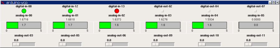
dokładnie opisane:
Improved Analog & Digital Interface with Arduino
http://emergent.unpythonic.net/01198594294