


Wie ktoś coś na temat tej płytki coś
Jakie arduino wybrać w ustawieniach
-
Wojtask
Autor tematu - Czytelnik forum poziom 1 (min. 10)
")
- Posty w temacie: 17
- Posty: 17
- Rejestracja: 24 gru 2021, 20:30
Wie ktoś coś na temat tej płytki coś
Witam jestem nowy wgrałem do tej płytki grbl 1.1 pod arduino uno i maszyna dziala poprawnie postanowiłem dodać krańcowki i tu jest problem płytka ich niewidzi albo pokazuje error zmieniam ustawienia w codzie i dalej nic żadnej reakcji niewiem czy dobre arduino wybrałem więc zacząłem szukać i pod innym arduino wgrałem i wtedy maszyna wogule inaczej zaczęła pracować wie ktoś jakie arduino wybrać do tej płytki. Wróciłem spowrotem do arduino uno ale bez dalszej zabawy w ustawieniach codu wydaje mi się że się ze cody systemowe nie odpowiadaj z pinamina plytce może sie mylę


-
 tuxcnc
- Lider FORUM (min. 2000)
")
- Posty w temacie: 7
- Posty: 7861
- Rejestracja: 26 lut 2011, 23:24
- Lokalizacja: mazowieckie
Re: Wie ktoś coś na temat tej płytki coś
Najpierw naucz się stawiać przecinki.Wojtask pisze: ↑24 gru 2021, 21:34Witam jestem nowy wgrałem do tej płytki grbl 1.1 pod arduino uno i maszyna dziala poprawnie postanowiłem dodać krańcowki i tu jest problem płytka ich niewidzi albo pokazuje error zmieniam ustawienia w codzie i dalej nic żadnej reakcji niewiem czy dobre arduino wybrałem więc zacząłem szukać i pod innym arduino wgrałem i wtedy maszyna wogule inaczej zaczęła pracować wie ktoś jakie arduino wybrać do tej płytki. Wróciłem spowrotem do arduino uno ale bez dalszej zabawy w ustawieniach codu wydaje mi się że się ze cody systemowe nie odpowiadaj z pinamina plytce może sie mylę
Mam problem z przecinkami - ale takiego zdania to nie widziałem
Jak masz problem z dysgrafią ( czy jak tam zwą).
Ja mam - nie umiem pisdać.
To pisz krótko - po żołniersku.
pzd.pukury
-
Wojtask
Autor tematu - Czytelnik forum poziom 1 (min. 10)
- Posty w temacie: 17
- Posty: 17
- Rejestracja: 24 gru 2021, 20:30
Re: Wie ktoś coś na temat tej płytki coś
Wiem że w pliku config.h muszę zmienić ale mi niewychodzi, czy ma ktoś plik na po dmiane, albo podpowiedzieć co jak i gdzie podmienić.
Dodane 45 minuty 32 sekundy:
Mam krancowki z LED i one się nie świecą tak jakby płytka ich niewykrywala
Dodane 45 minuty 32 sekundy:
Mam krancowki z LED i one się nie świecą tak jakby płytka ich niewykrywala
-
skmskm
- Specjalista poziom 2 (min. 300)
")
- Posty w temacie: 2
- Posty: 319
- Rejestracja: 15 lis 2014, 20:21
- Lokalizacja: Gliwice
Re: Wie ktoś coś na temat tej płytki coś
Do świecenia LED na nich nie potrzeba sterowania z płytki tylko zasilanie, .
W pliku config.h są tylko dwie opcje CPU_MAP_ATMEGA328P i CPU_MAP_ATMEGA2560.
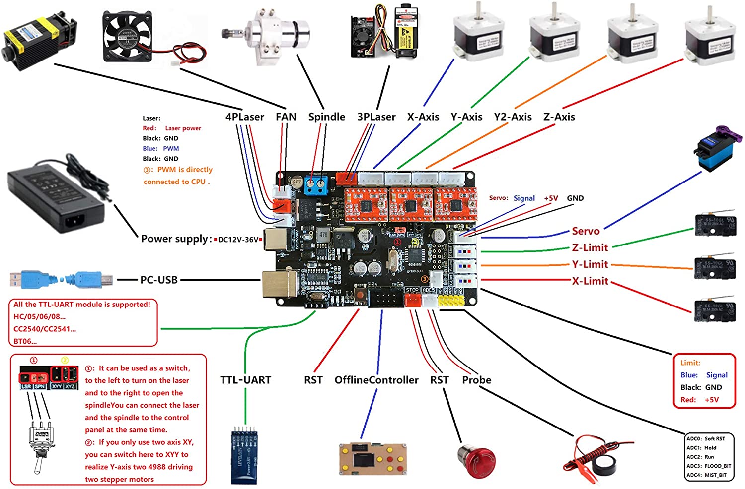
Z tego co widzę to ta płytka niema zasilania do krańcówek tylko dwa piny.(potrzeba 3 piny: GND,5V,Sygnał)
W pliku config.h są tylko dwie opcje CPU_MAP_ATMEGA328P i CPU_MAP_ATMEGA2560.
Z tego co widzę to ta płytka niema zasilania do krańcówek tylko dwa piny.(potrzeba 3 piny: GND,5V,Sygnał)
-
Wojtask
Autor tematu - Czytelnik forum poziom 1 (min. 10)
- Posty w temacie: 17
- Posty: 17
- Rejestracja: 24 gru 2021, 20:30
Re: Wie ktoś coś na temat tej płytki coś
Mam jeszcze taką płytkę i identyczny problem z krancowkami. Poda ktoś jak zmienić cod jakie to są linijki co muszę zrobić, dopiero zaczynam zabawę z programowaniem cnc.
Dodane 12 minuty 23 sekundy:
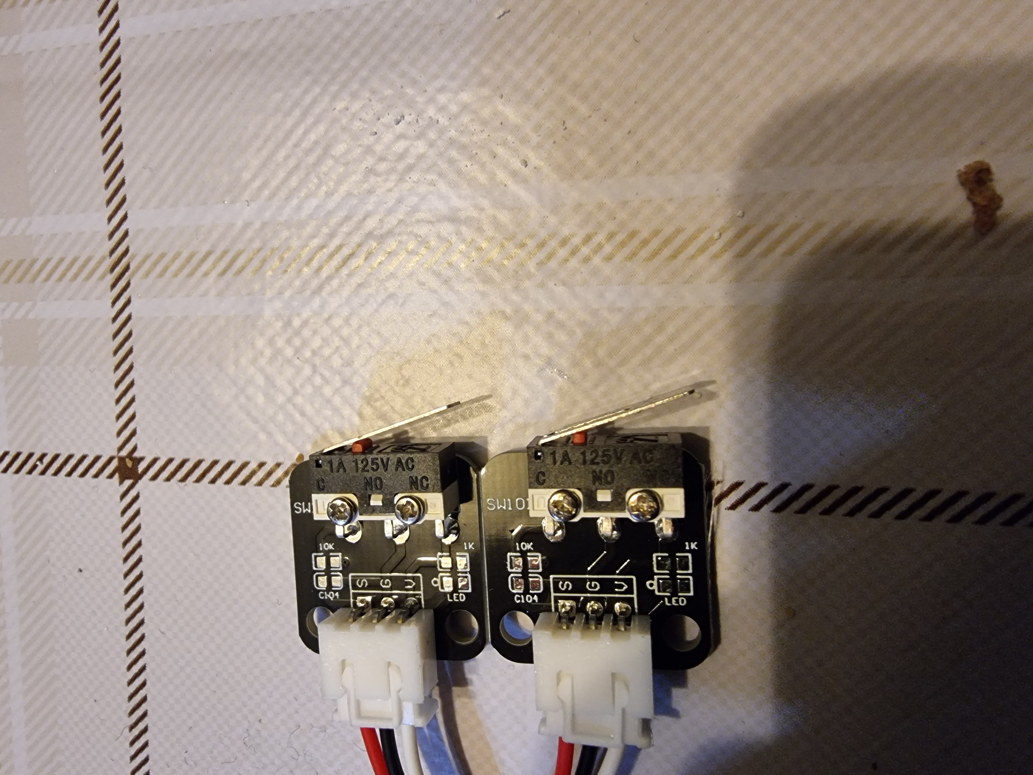
Takie krancowki
Dodane 2 minuty 40 sekundy:
Co i na co muszę zamienić
Wiem że w pliku config.h muszę zmienić ale mi niewychodzi.
-
tuxcnc
- Lider FORUM (min. 2000)
- Posty w temacie: 7
- Posty: 7861
- Rejestracja: 26 lut 2011, 23:24
- Lokalizacja: mazowieckie
Re: Wie ktoś coś na temat tej płytki coś
Po pierwsze, na płytkach brakuje elementów, być może nigdy nie były wlutowane.
Jest to o tyle ważne, że trudno się spodziewać, żeby świeciła dioda której nie ma.
Natomiast bez tych elementów też będzie działać, tylko trochę gorzej.
Szczególnie brak filtra przeciwzakłóceniowego może stwarzać problemy, brak LED-a można przeboleć.
Nie wszystko widzę dokładnie, ale jest tam mechaniczny przełącznik podłączony w układzie rail-to-rail, czyli wyjście raz jest zwierane z masą, a raz z plusem zasilania.
Wygląda na to, że oznaczenia należy rozumieć w ten sposób:
S - sygnał wyjściowy
V - +5 woltów
G - masa
Na twoim miejscu +5 V bym nie podłączał, bo wtedy łatwo coś przez nieuwagę spalić.
Użyj wyjść G i S, czyli kabelków czerwonego i czarnego, wpinając je pomiędzy GND płytki i wejście krańcówki.
-
 TOP67
TOP67
- Lider FORUM (min. 2000)
- Posty w temacie: 12
- Posty: 2224
- Rejestracja: 17 wrz 2018, 10:47
- Lokalizacja: Wrocław
- Kontakt:
Re: Wie ktoś coś na temat tej płytki coś
Na pierwszej płytce masz krańcówki podpinane dwoma przewodami. Niech Cię nie zmylą napisy X+ i X-, one są zwarte ze sobą i służą do podłączenia krańcówek na obu końcach osi. Swoją podłącz do dowolnego pinu, a drugi kabel do tego poniżej, czyli masy (tu zwarte są wszyskie). Kable, tak jak napisano S i G (swoją drogą, czerwony zwykle daje się do zasilania).
Natomiast w drugiej płytce masz wyjścia 3 pinowe, zapewne do krańcówek z optoizolacją.
Natomiast w drugiej płytce masz wyjścia 3 pinowe, zapewne do krańcówek z optoizolacją.
-
Wojtask
Autor tematu - Czytelnik forum poziom 1 (min. 10)
- Posty w temacie: 17
- Posty: 17
- Rejestracja: 24 gru 2021, 20:30
Re: Wie ktoś coś na temat tej płytki coś
Co tu zmienć
/*
config.h - compile time configuration
Part of Grbl
Copyright (c) 2012-2015 Sungeun K. Jeon
Copyright (c) 2009-2011 Simen Svale Skogsrud
Grbl is free software: you can redistribute it and/or modify
it under the terms of the GNU General Public License as published by
the Free Software Foundation, either version 3 of the License, or
(at your option) any later version.
Grbl is distributed in the hope that it will be useful,
but WITHOUT ANY WARRANTY; without even the implied warranty of
MERCHANTABILITY or FITNESS FOR A PARTICULAR PURPOSE. See the
GNU General Public License for more details.
You should have received a copy of the GNU General Public License
along with Grbl. If not, see <http://www.gnu.org/licenses/>.
*/
// This file contains compile-time configurations for Grbl's internal system. For the most part,
// users will not need to directly modify these, but they are here for specific needs, i.e.
// performance tuning or adjusting to non-typical machines.
// IMPORTANT: Any changes here requires a full re-compiling of the source code to propagate them.
#ifndef config_h
#define config_h
#include "grbl.h" // For Arduino IDE compatibility.
// Default settings. Used when resetting EEPROM. Change to desired name in defaults.h
#define DEFAULTS_GENERIC
// Serial baud rate
#define BAUD_RATE 115200
// Default cpu mappings. Grbl officially supports the Arduino Uno only. Other processor types
// may exist from user-supplied templates or directly user-defined in cpu_map.h
#define CPU_MAP_ATMEGA328P // Arduino Uno CPU
// Define realtime command special characters. These characters are 'picked-off' directly from the
// serial read data stream and are not passed to the grbl line execution parser. Select characters
// that do not and must not exist in the streamed g-code program. ASCII control characters may be
// used, if they are available per user setup. Also, extended ASCII codes (>127), which are never in
// g-code programs, maybe selected for interface programs.
// NOTE: If changed, manually update help message in report.c.
#define CMD_STATUS_REPORT '?'
#define CMD_FEED_HOLD '!'
#define CMD_CYCLE_START '~'
#define CMD_RESET 0x18 // ctrl-x.
#define CMD_SAFETY_DOOR '@'
// If homing is enabled, homing init lock sets Grbl into an alarm state upon power up. This forces
// the user to perform the homing cycle (or override the locks) before doing anything else. This is
// mainly a safety feature to remind the user to home, since position is unknown to Grbl.
#define HOMING_INIT_LOCK // Comment to disable
// Define the homing cycle patterns with bitmasks. The homing cycle first performs a search mode
// to quickly engage the limit switches, followed by a slower locate mode, and finished by a short
// pull-off motion to disengage the limit switches. The following HOMING_CYCLE_x defines are executed
// in order starting with suffix 0 and completes the homing routine for the specified-axes only. If
// an axis is omitted from the defines, it will not home, nor will the system update its position.
// Meaning that this allows for users with non-standard cartesian machines, such as a lathe (x then z,
// with no y), to configure the homing cycle behavior to their needs.
// NOTE: The homing cycle is designed to allow sharing of limit pins, if the axes are not in the same
// cycle, but this requires some pin settings changes in cpu_map.h file. For example, the default homing
// cycle can share the Z limit pin with either X or Y limit pins, since they are on different cycles.
// By sharing a pin, this frees up a precious IO pin for other purposes. In theory, all axes limit pins
// may be reduced to one pin, if all axes are homed with seperate cycles, or vice versa, all three axes
// on separate pin, but homed in one cycle. Also, it should be noted that the function of hard limits
// will not be affected by pin sharing.
// NOTE: Defaults are set for a traditional 3-axis CNC machine. Z-axis first to clear, followed by X & Y.
#define HOMING_CYCLE_0 (1<<Z_AXIS) // REQUIRED: First move Z to clear workspace.
#define HOMING_CYCLE_1 ((1<<X_AXIS)|(1<<Y_AXIS)) // OPTIONAL: Then move X,Y at the same time.
// #define HOMING_CYCLE_2 // OPTIONAL: Uncomment and add axes mask to enable
// Number of homing cycles performed after when the machine initially jogs to limit switches.
// This help in preventing overshoot and should improve repeatability. This value should be one or
// greater.
#define N_HOMING_LOCATE_CYCLE 1 // Integer (1-128)
// After homing, Grbl will set by default the entire machine space into negative space, as is typical
// for professional CNC machines, regardless of where the limit switches are located. Uncomment this
// define to force Grbl to always set the machine origin at the homed location despite switch orientation.
// #define HOMING_FORCE_SET_ORIGIN // Uncomment to enable.
// Number of blocks Grbl executes upon startup. These blocks are stored in EEPROM, where the size
// and addresses are defined in settings.h. With the current settings, up to 2 startup blocks may
// be stored and executed in order. These startup blocks would typically be used to set the g-code
// parser state depending on user preferences.
#define N_STARTUP_LINE 2 // Integer (1-2)
// Number of floating decimal points printed by Grbl for certain value types. These settings are
// determined by realistic and commonly observed values in CNC machines. For example, position
// values cannot be less than 0.001mm or 0.0001in, because machines can not be physically more
// precise this. So, there is likely no need to change these, but you can if you need to here.
// NOTE: Must be an integer value from 0 to ~4. More than 4 may exhibit round-off errors.
#define N_DECIMAL_COORDVALUE_INCH 4 // Coordinate or position value in inches
#define N_DECIMAL_COORDVALUE_MM 3 // Coordinate or position value in mm
#define N_DECIMAL_RATEVALUE_INCH 1 // Rate or velocity value in in/min
#define N_DECIMAL_RATEVALUE_MM 0 // Rate or velocity value in mm/min
#define N_DECIMAL_SETTINGVALUE 3 // Decimals for floating point setting values
// If your machine has two limits switches wired in parallel to one axis, you will need to enable
// this feature. Since the two switches are sharing a single pin, there is no way for Grbl to tell
// which one is enabled. This option only effects homing, where if a limit is engaged, Grbl will
// alarm out and force the user to manually disengage the limit switch. Otherwise, if you have one
// limit switch for each axis, don't enable this option. By keeping it disabled, you can perform a
// homing cycle while on the limit switch and not have to move the machine off of it.
// #define LIMITS_TWO_SWITCHES_ON_AXES
// Allows GRBL to track and report gcode line numbers. Enabling this means that the planning buffer
// goes from 18 or 16 to make room for the additional line number data in the plan_block_t struct
// #define USE_LINE_NUMBERS // Disabled by default. Uncomment to enable.
// Allows GRBL to report the real-time feed rate. Enabling this means that GRBL will be reporting more
// data with each status update.
// NOTE: This is experimental and doesn't quite work 100%. Maybe fixed or refactored later.
// #define REPORT_REALTIME_RATE // Disabled by default. Uncomment to enable.
// Upon a successful probe cycle, this option provides immediately feedback of the probe coordinates
// through an automatically generated message. If disabled, users can still access the last probe
// coordinates through Grbl '$#' print parameters.
#define MESSAGE_PROBE_COORDINATES // Enabled by default. Comment to disable.
// Enables a second coolant control pin via the mist coolant g-code command M7 on the Arduino Uno
// analog pin 4. Only use this option if you require a second coolant control pin.
// NOTE: The M8 flood coolant control pin on analog pin 3 will still be functional regardless.
// #define ENABLE_M7 // Disabled by default. Uncomment to enable.
// This option causes the feed hold input to act as a safety door switch. A safety door, when triggered,
// immediately forces a feed hold and then safely de-energizes the machine. Resuming is blocked until
// the safety door is re-engaged. When it is, Grbl will re-energize the machine and then resume on the
// previous tool path, as if nothing happened.
// #define ENABLE_SAFETY_DOOR_INPUT_PIN // Default disabled. Uncomment to enable.
// After the safety door switch has been toggled and restored, this setting sets the power-up delay
// between restoring the spindle and coolant and resuming the cycle.
// NOTE: Delay value is defined in milliseconds from zero to 65,535.
#define SAFETY_DOOR_SPINDLE_DELAY 4000
#define SAFETY_DOOR_COOLANT_DELAY 1000
// Enable CoreXY kinematics. Use ONLY with CoreXY machines.
// IMPORTANT: If homing is enabled, you must reconfigure the homing cycle #defines above to
// #define HOMING_CYCLE_0 (1<<X_AXIS) and #define HOMING_CYCLE_1 (1<<Y_AXIS)
// NOTE: This configuration option alters the motion of the X and Y axes to principle of operation
// defined at (http://corexy.com/theory.html). Motors are assumed to positioned and wired exactly as
// described, if not, motions may move in strange directions. Grbl requires the CoreXY A and B motors
// have the same steps per mm internally.
// #define COREXY // Default disabled. Uncomment to enable.
// Inverts pin logic of the control command pins. This essentially means when this option is enabled
// you can use normally-closed switches, rather than the default normally-open switches.
// NOTE: If you require individual control pins inverted, keep this macro disabled and simply alter
// the CONTROL_INVERT_MASK definition in cpu_map.h files.
// #define INVERT_ALL_CONTROL_PINS // Default disabled. Uncomment to enable.
// Inverts select limit pin states based on the following mask. This effects all limit pin functions,
// such as hard limits and homing. However, this is different from overall invert limits setting.
// This build option will invert only the limit pins defined here, and then the invert limits setting
// will be applied to all of them. This is useful when a user has a mixed set of limit pins with both
// normally-open(NO) and normally-closed(NC) switches installed on their machine.
// NOTE: PLEASE DO NOT USE THIS, unless you have a situation that needs it.
// #define INVERT_LIMIT_PIN_MASK ((1<<X_LIMIT_BIT)|(1<<Y_LIMIT_BIT)) // Default disabled. Uncomment to enable.
// Inverts the spindle enable pin from low-disabled/high-enabled to low-enabled/high-disabled. Useful
// for some pre-built electronic boards.
// NOTE: If VARIABLE_SPINDLE is enabled(default), this option has no effect as the PWM output and
// spindle enable are combined to one pin. If you need both this option and spindle speed PWM,
// uncomment the config option USE_SPINDLE_DIR_AS_ENABLE_PIN below.
// #define INVERT_SPINDLE_ENABLE_PIN // Default disabled. Uncomment to enable.
// Enable control pin states feedback in status reports. The data is presented as simple binary of
// the control pin port (0 (low) or 1(high)), masked to show only the input pins. Non-control pins on the
// port will always show a 0 value. See cpu_map.h for the pin bitmap. As with the limit pin reporting,
// we do not recommend keeping this option enabled. Try to only use this for setting up a new CNC.
// #define REPORT_CONTROL_PIN_STATE // Default disabled. Uncomment to enable.
// When Grbl powers-cycles or is hard reset with the Arduino reset button, Grbl boots up with no ALARM
// by default. This is to make it as simple as possible for new users to start using Grbl. When homing
// is enabled and a user has installed limit switches, Grbl will boot up in an ALARM state to indicate
// Grbl doesn't know its position and to force the user to home before proceeding. This option forces
// Grbl to always initialize into an ALARM state regardless of homing or not. This option is more for
// OEMs and LinuxCNC users that would like this power-cycle behavior.
// #define FORCE_INITIALIZATION_ALARM // Default disabled. Uncomment to enable.
// ---------------------------------------------------------------------------------------
// ADVANCED CONFIGURATION OPTIONS:
// Enables minimal reporting feedback mode for GUIs, where human-readable strings are not as important.
// This saves nearly 2KB of flash space and may allow enough space to install other/future features.
// GUIs will need to install a look-up table for the error-codes that Grbl sends back in their place.
// NOTE: This feature is new and experimental. Make sure the GUI you are using supports this mode.
// #define REPORT_GUI_MODE // Default disabled. Uncomment to enable.
// The temporal resolution of the acceleration management subsystem. A higher number gives smoother
// acceleration, particularly noticeable on machines that run at very high feedrates, but may negatively
// impact performance. The correct value for this parameter is machine dependent, so it's advised to
// set this only as high as needed. Approximate successful values can widely range from 50 to 200 or more.
// NOTE: Changing this value also changes the execution time of a segment in the step segment buffer.
// When increasing this value, this stores less overall time in the segment buffer and vice versa. Make
// certain the step segment buffer is increased/decreased to account for these changes.
#define ACCELERATION_TICKS_PER_SECOND 100
// Adaptive Multi-Axis Step Smoothing (AMASS) is an advanced feature that does what its name implies,
// smoothing the stepping of multi-axis motions. This feature smooths motion particularly at low step
// frequencies below 10kHz, where the aliasing between axes of multi-axis motions can cause audible
// noise and shake your machine. At even lower step frequencies, AMASS adapts and provides even better
// step smoothing. See stepper.c for more details on the AMASS system works.
#define ADAPTIVE_MULTI_AXIS_STEP_SMOOTHING // Default enabled. Comment to disable.
// Sets the maximum step rate allowed to be written as a Grbl setting. This option enables an error
// check in the settings module to prevent settings values that will exceed this limitation. The maximum
// step rate is strictly limited by the CPU speed and will change if something other than an AVR running
// at 16MHz is used.
// NOTE: For now disabled, will enable if flash space permits.
// #define MAX_STEP_RATE_HZ 30000 // Hz
// By default, Grbl sets all input pins to normal-high operation with their internal pull-up resistors
// enabled. This simplifies the wiring for users by requiring only a switch connected to ground,
// although its recommended that users take the extra step of wiring in low-pass filter to reduce
// electrical noise detected by the pin. If the user inverts the pin in Grbl settings, this just flips
// which high or low reading indicates an active signal. In normal operation, this means the user
// needs to connect a normal-open switch, but if inverted, this means the user should connect a
// normal-closed switch.
// The following options disable the internal pull-up resistors, sets the pins to a normal-low
// operation, and switches must be now connect to Vcc instead of ground. This also flips the meaning
// of the invert pin Grbl setting, where an inverted setting now means the user should connect a
// normal-open switch and vice versa.
// NOTE: All pins associated with the feature are disabled, i.e. XYZ limit pins, not individual axes.
// WARNING: When the pull-ups are disabled, this requires additional wiring with pull-down resistors!
//#define DISABLE_LIMIT_PIN_PULL_UP
//#define DISABLE_PROBE_PIN_PULL_UP
//#define DISABLE_CONTROL_PIN_PULL_UP
// Sets which axis the tool length offset is applied. Assumes the spindle is always parallel with
// the selected axis with the tool oriented toward the negative direction. In other words, a positive
// tool length offset value is subtracted from the current location.
#define TOOL_LENGTH_OFFSET_AXIS Z_AXIS // Default z-axis. Valid values are X_AXIS, Y_AXIS, or Z_AXIS.
// Enables variable spindle output voltage for different RPM values. On the Arduino Uno, the spindle
// enable pin will output 5V for maximum RPM with 256 intermediate levels and 0V when disabled.
// NOTE: IMPORTANT for Arduino Unos! When enabled, the Z-limit pin D11 and spindle enable pin D12 switch!
// The hardware PWM output on pin D11 is required for variable spindle output voltages.
#define VARIABLE_SPINDLE // Default enabled. Comment to disable.
// Used by the variable spindle output only. These parameters set the maximum and minimum spindle speed
// "S" g-code values to correspond to the maximum and minimum pin voltages. There are 256 discrete and
// equally divided voltage bins between the maximum and minimum spindle speeds. So for a 5V pin, 1000
// max rpm, and 250 min rpm, the spindle output voltage would be set for the following "S" commands:
// "S1000" @ 5V, "S250" @ 0.02V, and "S625" @ 2.5V (mid-range). The pin outputs 0V when disabled.
#define SPINDLE_MAX_RPM 1000.0 // Max spindle RPM. This value is equal to 100% duty cycle on the PWM.
#define SPINDLE_MIN_RPM 0.0 // Min spindle RPM. This value is equal to (1/256) duty cycle on the PWM.
// Used by variable spindle output only. This forces the PWM output to a minimum duty cycle when enabled.
// When disabled, the PWM pin will still read 0V. Most users will not need this option, but it may be
// useful in certain scenarios. This setting does not update the minimum spindle RPM calculations. Any
// spindle RPM output lower than this value will be set to this value.
// #define MINIMUM_SPINDLE_PWM 5 // Default disabled. Uncomment to enable. Integer (0-255)
// By default on a 328p(Uno), Grbl combines the variable spindle PWM and the enable into one pin to help
// preserve I/O pins. For certain setups, these may need to be separate pins. This configure option uses
// the spindle direction pin(D13) as a separate spindle enable pin along with spindle speed PWM on pin D11.
// NOTE: This configure option only works with VARIABLE_SPINDLE enabled and a 328p processor (Uno).
// NOTE: With no direction pin, the spindle clockwise M4 g-code command will be removed. M3 and M5 still work.
// NOTE: BEWARE! The Arduino bootloader toggles the D13 pin when it powers up. If you flash Grbl with
// a programmer (you can use a spare Arduino as "Arduino as ISP". Search the web on how to wire this.),
// this D13 LED toggling should go away. We haven't tested this though. Please report how it goes!
// #define USE_SPINDLE_DIR_AS_ENABLE_PIN // Default disabled. Uncomment to enable.
// With this enabled, Grbl sends back an echo of the line it has received, which has been pre-parsed (spaces
// removed, capitalized letters, no comments) and is to be immediately executed by Grbl. Echoes will not be
// sent upon a line buffer overflow, but should for all normal lines sent to Grbl. For example, if a user
// sendss the line 'g1 x1.032 y2.45 (test comment)', Grbl will echo back in the form '[echo: G1X1.032Y2.45]'.
// NOTE: Only use this for debugging purposes!! When echoing, this takes up valuable resources and can effect
// performance. If absolutely needed for normal operation, the serial write buffer should be greatly increased
// to help minimize transmission waiting within the serial write protocol.
// #define REPORT_ECHO_LINE_RECEIVED // Default disabled. Uncomment to enable.
// Minimum planner junction speed. Sets the default minimum junction speed the planner plans to at
// every buffer block junction, except for starting from rest and end of the buffer, which are always
// zero. This value controls how fast the machine moves through junctions with no regard for acceleration
// limits or angle between neighboring block line move directions. This is useful for machines that can't
// tolerate the tool dwelling for a split second, i.e. 3d printers or laser cutters. If used, this value
// should not be much greater than zero or to the minimum value necessary for the machine to work.
#define MINIMUM_JUNCTION_SPEED 0.0 // (mm/min)
// Sets the minimum feed rate the planner will allow. Any value below it will be set to this minimum
// value. This also ensures that a planned motion always completes and accounts for any floating-point
// round-off errors. Although not recommended, a lower value than 1.0 mm/min will likely work in smaller
// machines, perhaps to 0.1mm/min, but your success may vary based on multiple factors.
#define MINIMUM_FEED_RATE 1.0 // (mm/min)
// Number of arc generation iterations by small angle approximation before exact arc trajectory
// correction with expensive sin() and cos() calcualtions. This parameter maybe decreased if there
// are issues with the accuracy of the arc generations, or increased if arc execution is getting
// bogged down by too many trig calculations.
#define N_ARC_CORRECTION 12 // Integer (1-255)
// The arc G2/3 g-code standard is problematic by definition. Radius-based arcs have horrible numerical
// errors when arc at semi-circles(pi) or full-circles(2*pi). Offset-based arcs are much more accurate
// but still have a problem when arcs are full-circles (2*pi). This define accounts for the floating
// point issues when offset-based arcs are commanded as full circles, but get interpreted as extremely
// small arcs with around machine epsilon (1.2e-7rad) due to numerical round-off and precision issues.
// This define value sets the machine epsilon cutoff to determine if the arc is a full-circle or not.
// NOTE: Be very careful when adjusting this value. It should always be greater than 1.2e-7 but not too
// much greater than this. The default setting should capture most, if not all, full arc error situations.
#define ARC_ANGULAR_TRAVEL_EPSILON 5E-7 // Float (radians)
// Time delay increments performed during a dwell. The default value is set at 50ms, which provides
// a maximum time delay of roughly 55 minutes, more than enough for most any application. Increasing
// this delay will increase the maximum dwell time linearly, but also reduces the responsiveness of
// run-time command executions, like status reports, since these are performed between each dwell
// time step. Also, keep in mind that the Arduino delay timer is not very accurate for long delays.
#define DWELL_TIME_STEP 50 // Integer (1-255) (milliseconds)
// Creates a delay between the direction pin setting and corresponding step pulse by creating
// another interrupt (Timer2 compare) to manage it. The main Grbl interrupt (Timer1 compare)
// sets the direction pins, and does not immediately set the stepper pins, as it would in
// normal operation. The Timer2 compare fires next to set the stepper pins after the step
// pulse delay time, and Timer2 overflow will complete the step pulse, except now delayed
// by the step pulse time plus the step pulse delay. (Thanks langwadt for the idea!)
// NOTE: Uncomment to enable. The recommended delay must be > 3us, and, when added with the
// user-supplied step pulse time, the total time must not exceed 127us. Reported successful
// values for certain setups have ranged from 5 to 20us.
// #define STEP_PULSE_DELAY 10 // Step pulse delay in microseconds. Default disabled.
// The number of linear motions in the planner buffer to be planned at any give time. The vast
// majority of RAM that Grbl uses is based on this buffer size. Only increase if there is extra
// available RAM, like when re-compiling for a Mega or Sanguino. Or decrease if the Arduino
// begins to crash due to the lack of available RAM or if the CPU is having trouble keeping
// up with planning new incoming motions as they are executed.
// #define BLOCK_BUFFER_SIZE 18 // Uncomment to override default in planner.h.
// Governs the size of the intermediary step segment buffer between the step execution algorithm
// and the planner blocks. Each segment is set of steps executed at a constant velocity over a
// fixed time defined by ACCELERATION_TICKS_PER_SECOND. They are computed such that the planner
// block velocity profile is traced exactly. The size of this buffer governs how much step
// execution lead time there is for other Grbl processes have to compute and do their thing
// before having to come back and refill this buffer, currently at ~50msec of step moves.
// #define SEGMENT_BUFFER_SIZE 6 // Uncomment to override default in stepper.h.
// Line buffer size from the serial input stream to be executed. Also, governs the size of
// each of the startup blocks, as they are each stored as a string of this size. Make sure
// to account for the available EEPROM at the defined memory address in settings.h and for
// the number of desired startup blocks.
// NOTE: 80 characters is not a problem except for extreme cases, but the line buffer size
// can be too small and g-code blocks can get truncated. Officially, the g-code standards
// support up to 256 characters. In future versions, this default will be increased, when
// we know how much extra memory space we can re-invest into this.
// #define LINE_BUFFER_SIZE 80 // Uncomment to override default in protocol.h
// Serial send and receive buffer size. The receive buffer is often used as another streaming
// buffer to store incoming blocks to be processed by Grbl when its ready. Most streaming
// interfaces will character count and track each block send to each block response. So,
// increase the receive buffer if a deeper receive buffer is needed for streaming and avaiable
// memory allows. The send buffer primarily handles messages in Grbl. Only increase if large
// messages are sent and Grbl begins to stall, waiting to send the rest of the message.
// NOTE: Buffer size values must be greater than zero and less than 256.
// #define RX_BUFFER_SIZE 128 // Uncomment to override defaults in serial.h
// #define TX_BUFFER_SIZE 64
// Toggles XON/XOFF software flow control for serial communications. Not officially supported
// due to problems involving the Atmega8U2 USB-to-serial chips on current Arduinos. The firmware
// on these chips do not support XON/XOFF flow control characters and the intermediate buffer
// in the chips cause latency and overflow problems with standard terminal programs. However,
// using specifically-programmed UI's to manage this latency problem has been confirmed to work.
// As well as, older FTDI FT232RL-based Arduinos(Duemilanove) are known to work with standard
// terminal programs since their firmware correctly manage these XON/XOFF characters. In any
// case, please report any successes to grbl administrators!
// #define ENABLE_XONXOFF // Default disabled. Uncomment to enable.
// A simple software debouncing feature for hard limit switches. When enabled, the interrupt
// monitoring the hard limit switch pins will enable the Arduino's watchdog timer to re-check
// the limit pin state after a delay of about 32msec. This can help with CNC machines with
// problematic false triggering of their hard limit switches, but it WILL NOT fix issues with
// electrical interference on the signal cables from external sources. It's recommended to first
// use shielded signal cables with their shielding connected to ground (old USB/computer cables
// work well and are cheap to find) and wire in a low-pass circuit into each limit pin.
// #define ENABLE_SOFTWARE_DEBOUNCE // Default disabled. Uncomment to enable.
// Force Grbl to check the state of the hard limit switches when the processor detects a pin
// change inside the hard limit ISR routine. By default, Grbl will trigger the hard limits
// alarm upon any pin change, since bouncing switches can cause a state check like this to
// misread the pin. When hard limits are triggered, they should be 100% reliable, which is the
// reason that this option is disabled by default. Only if your system/electronics can guarantee
// that the switches don't bounce, we recommend enabling this option. This will help prevent
// triggering a hard limit when the machine disengages from the switch.
// NOTE: This option has no effect if SOFTWARE_DEBOUNCE is enabled.
// #define HARD_LIMIT_FORCE_STATE_CHECK // Default disabled. Uncomment to enable.
// ---------------------------------------------------------------------------------------
// COMPILE-TIME ERROR CHECKING OF DEFINE VALUES:
#ifndef HOMING_CYCLE_0
#error "Required HOMING_CYCLE_0 not defined."
#endif
#if defined(USE_SPINDLE_DIR_AS_ENABLE_PIN) && !defined(VARIABLE_SPINDLE)
#error "USE_SPINDLE_DIR_AS_ENABLE_PIN may only be used with VARIABLE_SPINDLE enabled"
#endif
#if defined(USE_SPINDLE_DIR_AS_ENABLE_PIN) && !defined(CPU_MAP_ATMEGA328P)
#error "USE_SPINDLE_DIR_AS_ENABLE_PIN may only be used with a 328p processor"
#endif
// ---------------------------------------------------------------------------------------
#endif