smoothstepper + m542

Rozmowy na temat układów elektronicznych sterowania obrabiarek CNC

Autor tematu
gralu
Nowy użytkownik, używaj wyszukiwarki
Posty w temacie: 2
Posty: 7
Rejestracja: 31 mar 2008, 23:14
Lokalizacja: szczecin

smoothstepper + m542

#1

Post napisał: gralu » 29 gru 2008, 18:07

Witam

Jako, że w temacie CNC jestem początkujący, postanowiłem zasięgnąć opinii fachowców.
Jestem w posiadaniu sterownika USB Smoothstepper i dobrze Wam znanych sterowników silników krokowych M542 (2 osie), które chce podłączyć z pominięciem Breakout Board (BOB).
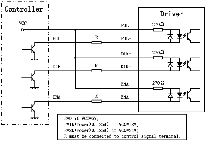
Czy jest osoba na forum, która może mi wyjaśnić jak wykonać krok po kroku, połączenia sygnałowe PUL +/-, DIR +/-, ENA +/- dla 2 sterowników M542 wpiętych do Portu 1?
Jak na przejściówkę LPT=>USB jest dość droga, więc pominę testy na własną rękę, żeby nie upalić czegoś przedwcześnie.
Będę bardzo wdzięczny za tutorial, cenne wskazówki.

Pozdrawiam

Instrukcja Smoothstepper

schemat M542

Obrazek


Tagi:


Goose
Znawca tematu (min. 80)
Posty w temacie: 1
Posty: 99
Rejestracja: 13 gru 2006, 20:17
Lokalizacja: Myslowice

#2

Post napisał: Goose » 30 gru 2008, 20:43

Smoothsteper to inaczej port LPT na USB z mozliwoscia wysylania segnalow o czestotliwosci 256 kHz.

Niestety, plyte glowna musisz kupic. :roll:

Cytat z dokumentacji Smoothsteppera:

Z sekcji 7.0:
"The SmoothStepper is intended to be used with breakout boards that make it easier to wire motors
and switches,"
Z sekscji 7.2:
"The SmoothStepper was designed to be a parallel port replacement."


Autor tematu
gralu
Nowy użytkownik, używaj wyszukiwarki
Posty w temacie: 2
Posty: 7
Rejestracja: 31 mar 2008, 23:14
Lokalizacja: szczecin

#3

Post napisał: gralu » 30 gru 2008, 21:19

w pełni się z Tobą zgadzam, że SS to taki "akcelerator" portu LPT...
z dobrze poinformowanych mi źródeł (m.in. expert z tego forum) wiem, że płyta główna BOB pełni tylko funkcję pośrednika, ułatwiającego połączenie i optoizolację, stad wnioskuję, że można skutecznie ją pominąć, stosując sterowniki z wbudowaną optoizolacją...

jak wynika z instrukcji SS i cytatów, które wkleiłeś, BOB umożliwia łatwiejsze podłączenie sterowników, co nie znaczy, że bez nich nie da się ich podłączyć...

jeżeli się mylę to mnie poprawcie:

- wyprowadzamy odpowiednie połączenia PUL "-" i DIR "-" z PINów SS ustawionych odpowiednio w MACH3, PORT1, dla pierwszej i drugiej osi;
- na płycie SS zwieramy zworę (rzut SS w manualu, zwora nad złaczemi portów) i podajemy napięcie +5V na PIN 26 PORT1 1, gdzie mostkujemy go dla PUL "+" i DIR "+";
- ENA pozostawiamy niepodłączone

czy to jest dobre rozumowanie, czy kompletnie bez sensu?! jeżeli ktoś uważa, że takie podłączenie ma szanse coś upalić to niech napisze, w przeciwnym razie zacznę jakieś testy ;)

Awatar użytkownika

wacek007
Specjalista poziom 1 (min. 100)
Posty w temacie: 3
Posty: 100
Rejestracja: 05 mar 2007, 20:24
Lokalizacja: Czestochowa

#4

Post napisał: wacek007 » 06 lut 2009, 17:32

wszystko fajnie, ale ja bym raczej polecał optoizolacje, nawet jeśli masz w serownikach to przydało by się odizolować karańcówki. SS jest bardzo czuły na wszelkie szumy. Jeśli zacznie gubić transmisje (czasem bywa), to znak, że czas zacząć kombinacje z uziemieniami a nawet izolacją usb. Moim zdaniem najsłabszym ogniwem SS jest układ FTDI. wcale nie tak trudno go upalić.

Awatar użytkownika

markcomp77
Lider FORUM (min. 2000)
Posty w temacie: 1
Posty: 3975
Rejestracja: 18 wrz 2004, 12:51
Lokalizacja: k/w-wy
Kontakt:

#5

Post napisał: markcomp77 » 06 lut 2009, 17:47

izolacja USB to faktycznie niezły pomysł...
fajnie było by również zasilać SS... a nie obciążać PCeta, bo zdarzają się takie którym brak powera to zasilić...
oczywiście zasilać SS z niezależnego zasilacza - tylko dla niego
SpotkanieCNC: STOM-TOOL Marzec 2014
http://www.cnc.info.pl/topics79/spotkan ... t55028.htm

Awatar użytkownika

wacek007
Specjalista poziom 1 (min. 100)
Posty w temacie: 3
Posty: 100
Rejestracja: 05 mar 2007, 20:24
Lokalizacja: Czestochowa

#6

Post napisał: wacek007 » 06 lut 2009, 19:52

Pomysł dobry, ale napewno nie tani, bo nie wiem czy unas się dostanie odpowiednie adaptery usb.
To jest treść maila, którego dostałem po zgłoszeniu problemów z przerywaniem transmisji (na szczęście tylko raz się to stało i nie w czasie pracy). sądze, że to szablon który produceny już wielu osobom wysyłał, bo ja bym wolał zwrócić pieniądze niż tyle pisać :wink:

I am not certain of the solution, though I have strong feelings that it
is a ground loop problem. I think that the loop is formed like this:

ground of the PC -> USB cable -> SS -> ground at the SS -> ground
through the system -> ground of the PC.

There are a number of things you can try. Some of them are cheap, and
some expensive. In the warp9td forum, someone said they had success
with running the SS with a laptop which was powered by batteries. Then
they tried the desktop computer without the earth ground connected.
Disconnecting the earth ground is not something I recommend because of
safety reasons, but in this person's experiment, it fixed the problem
(which was the communications getting killed when the spindle turned on
(I think)). What it tells me is that there is a ground loop that must
be broken. An expensive solution is to purchase an isolated USB
interface. Here is a link to a company that sells such a link:

http://opticis.com/english/02_product/product03_01.htm

It looks like they have distributors worldwide:
http://opticis.com/english/04_distribut ... ibutor.htm

I was just looking at the website of one of the distributors, and I
found the following (http://industrialcomponent.com/developers.html):

----------------------------------------------------------------
Here's a hardware design tip that is the coming thing ...

* Input Power: If your product is aimed at the international as well as
domestic markets, especially for mobile operation, use a power supply
"brick" that will work from 100 to 240 VAC, 50 to 60 Hertz and is of the
"two blade" variety (isolated, no ground prong). This helps during
"brown outs" and power surges and is easy to use overseas without
inverters. These "universal" or "international" power supplies can work
just about anywhere in the "first and second world" and most of the
"third world". This will save a significant number of support phone
calls and requests for unprofitable, optional supplies. Don't reinvent
the wheel here ... it will increase inventory costs, tech support and
sales grief later.

* Output Power: If possible, make the output voltage from the power
supply brick 11 to 14 VDC, and less than 500 milliamps. This will match
the power from 12 VDC, auto, truck and solar power adapters. This makes
your gadget "mobile". You may have add DC regulation on your circuit
board to accommodate this, although many USB and FireWire 1394 chip sets
have this on board regulation.
----------------------------------------------------------------

Interesting that they recommend an isolated supply ;-)

Another potential solution is to minimize the voltage drop from the PC
to the SS. Adding a heavy ground from the PC to the SS will help. My
suspicion is that the ground loop stills exists, but it doesn't matter
if there is a current flowing through the ground if the impedance from
the PC to the SS is very low. Voltage drop across the cable is equal to
the current times the impedance (resistance). Minimize the impedance
and the voltage drop decreases the same amount. Unfortunately, USB is
not a purely differential signaling standard. There is a part of the
protocol that references the signals to ground. That is too bad, and is
probably the reason why this is happening. Adding a heavy ground wire
in parallel with the USB cable (power supply ground from a hard drive
connector, connected to the SS's ground) might help matters.

Some people have reported good success with using a USB host adapter
with a chip from NEC. I guess all USB interfaces are not equal, and NEC
has done a good job of implementing USB. Here is a link to a company
that advertises a cable that uses an NEC chip:

http://www.usbgear.com/computer_cable_d ... C120%2C137

I believe that an extension cable such as this is really just a USB hub
chip with only one downstream port. You might be able to solve the
disconnect problem by putting a self-powered USB hub in between the SS
and the PC. Others have found a lot of success doing that. Others have
found success disabling the computer's ability to disable a USB port to
save power. Is there any chance it could be that the computer is
turning off the power to the USB in order to save power? You can turn
this feature off if that is the problem. Some users in the Mach Yahoo
Group have found this to help:

The following instructions are for XP. If you go into Device Manager
(Start -> Run -> devmgmt.msc), you will see "Universal Serial Bus
Controllers". Once Device Manager is open, look near the bottom for
"Universal Serial Bus Controllers". Expanding this will reveal a number
of "USB Root Hub" items to select from. If you select one and
right-click on it, you will have the option of "Properties". When you do
this, a dialog will pop up with 5 tabs. One of them is "Power
Management". Selecting this reveals an option that says "Allow the
computer to turn off this device to save power". De-select this. I
noticed there is another tab named "Power". Selecting this tab may help
in identifying which USB connector is associated with which Root Hub. I
plugged a Microsoft Mouse into each port to help determine which one was
which. You might want to allow some of the root hubs to be able to turn
off the power.

Another possible solution is to remove the capacitor and the resistor
right next to the USB connector, opposite the side with the LEDs. The
reference designators are "C4" and "R5". These connect the cable shield
to the ground of the SS. I have one report of this fixing the problem,
and one report that it did not. Shields should only be connected at one
end. Typically this is done at the signal source. In the case of USB
it is bidirectional, so both ends are the source and the destination.
So I think the host side is usually the end that is grounded. The SS
side is not a direct ground. AC transient signals can pass through the
capacitor to ground, while not providing a DC connection. The resistor
is in parallel with the capacitor, but the value is 10 MegaOhms, which
is very high. Basically its intended purpose was to bleed DC charge
away over time. Kind of like a lightning rod. I found this circuit on
a website when I was designing the board. Most reference designs that I
saw did not have such a circuit, and I am questioning whether or not
they are doing more harm than good. If you removed these components, I
don't think you would be hurting the SS. In fact you would be making
the design similar to the majority of USB designs out there. Or you
might
find success by adding another capacitor across the existing one. Noise
is black magic.

Please let me know if this does not help. I feel that if you think very
hard about where the currents are flowing, you will find that you do not
have a "star ground". You do not want ground loops. Ground should be
located at a single point and radiate out like a star.

[ Dodano: 2009-02-07, 14:35 ]
Wytestuje połączenie ss przez takiego huba http://www.allegro.pl/item545626539_hub ... _gwar.html , z zewnętrznym zasilaniem 5V. zastanawiam się tylko czy SS i tego huba wpiąć w jeden zasilacz.
A ma ktoś może jakieś opinie o portach USB na PCI ? Czy mogło by to wogóle dać jakieś wymierne korzyści?

jarekk
ELITA FORUM (min. 1000)
Posty w temacie: 1
Posty: 1701
Rejestracja: 17 mar 2006, 08:57
Lokalizacja: Gdańsk

#7

Post napisał: jarekk » 07 lut 2009, 20:13

Jeżeli problem z SS jest elektryczny, to hub raczej nie pomoże.

A co do USB na PCI - nie powinno być różnicy w stosunku do USB na płycie ( te na płycie też są na wewnętrznej magistrali PCI ).

[ Dodano: 2009-02-07, 20:14 ]
Prościej jest chyba niestety izolować cały komputer sygnały z SS przez optoizolacje :-(

Awatar użytkownika

wacek007
Specjalista poziom 1 (min. 100)
Posty w temacie: 3
Posty: 100
Rejestracja: 05 mar 2007, 20:24
Lokalizacja: Czestochowa

#8

Post napisał: wacek007 » 07 lut 2009, 22:21

Jaknajbardziej, łącze ss przez adapter LPT, bardzo fajny wobitowski (300 PLN :roll: ), pełna izolacja, filtry sygnałów wejściowych i takie tam...
Według autora ss problem jest z uziemieniem, a konkretnie jak on to napisał groundloop, czyli w moim rozumieniu napięcie zamiaz spływać do ziemi zaczyna krążyć po systemie i moim zdaniem FTDI pracuje wtedy niestabilnie. Dlatego doradza zakładać izolacje wszędzie tam gdzie się da :cool:
z prostych rozwiazań sensownym wydaje się usunięcie rezystorów obok złącza usb. teoretycznie powinno to przerwać obieg uziemienia.
Ja tam nie lubie niczego robić po omacku i chciałbym wydedukować konkretne rozwiązanie. Zresztą myśle, że to nie tylko mój problem. Jest pare postów z podobnymi skargami, a zwis kontrolera w czasie pracy jest na prawde opłakany w skutkach. Kontroler dalej generuje krok w nieskończoność i tragedia gotowa


b_j
Specjalista poziom 2 (min. 300)
Posty w temacie: 1
Posty: 301
Rejestracja: 04 mar 2006, 22:36
Lokalizacja: poznan

#9

Post napisał: b_j » 10 mar 2009, 21:20

witam, panowie , jeżeli przerywa wam połączenia z SS - to może pomoże mój problem z SS , który udało sie rozwiązać. Mozecie sie zapoznać ze szczegółami w moim topicu ... https://www.cnc.info.pl/topics45/zawies ... t12826.htm
Mogło sie zdarzyc ze koledze tylko raz przerwało połączenie bo akurat np. przez dłuższy czas nie dotykał myszki albo od drgan sama sie nie przesunęła :D


cnc3d
Specjalista poziom 3 (min. 600)
Posty w temacie: 1
Posty: 635
Rejestracja: 29 mar 2008, 16:48
Lokalizacja: laski

#10

Post napisał: cnc3d » 11 mar 2009, 07:27

USB się do sterowania maszyn po prostu nie nadaje. I choćbyśmy stawali na głowie, to margines bezoieczeństwa w transmisji USB jest bardzo niewielki, a zakłucenia potrafią bardzo łatwo zerwać transmisję. Problem występuje w szczególności z układami FTDI i ich driwerem, który pod działaniem zakłuceń się po prostu zawiesza. Producent FTDI ma to raczej w nosie, ponieważ układ jest przewidziany do mniej wymagających aplikacji, a jego podstawową cechą jest łatwość implementacji do układu, udając po prostu standardową magistralę szeregową lub równolwgłą. Inną sprawą jest to, że takie podejście wielokrotnie ogranicza przepustowość tego kanału. Są oczywiście układy lepsze, odporniejsze, szybsze i tańsze, ale ich obsługa jest skomplikowana. Czy ktoś widział FTDI w jakiejś drukarce, lub innym urządzeniu powszechnego użytku? Raczej nie.
Przykład z życia: Maszyna pracowała przy lotnisku. W nocy maszyna pracowała bez problemu, a od rana jak powłączali radary i system naprowadzania co chwilę zrywało połączenie USB ze sterownikiem.

ODPOWIEDZ Poprzedni tematNastępny temat

Wróć do „Elektronika CNC”